Can Two Network Interfaces Have the Same Ip Address?
Case 1: Connecting to One Public and I Individual Network
In this scenario, a host PC is connected to both a corporate network (via NIC #one) which allows cyberspace admission as well every bit a private network (via NIC #ii) with several LabVIEW Existent-Time targets. The corporate network is setup to assign a DHCP address in the range of 10.0.10.x with subnet mask 255.255.0.0 to NIC #1. The default gateway (router) address is 10.0.0.1.
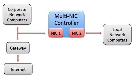
Figure 5. In this scenario, a multi-NIC controller is connected to both a corporate network (with internet access) and a local private network.
Post-obit the guidelines in a higher place, nosotros tin can configure NIC #2, attached to the private network, with a static IP outside of the 10.0.x.ten subnet range. While information technology might exist acceptable to employ an address in the 10.one.x.10 range, as information technology is in a different subnet, it is possible that other ten.x.x.x IP addresses are used for additional corporate servers, etc. Therefore, it is safer to employ the 192.168.ten.10 range for the private network.
Since we are working with a small number of LabVIEW Real-Time targets in the private network, we can use a subnet mask of 255.255.255.0 and assign each a static IP address in the range 192.168.0.x; this will allow for upward to 255 connected interfaces in the subnet. For simplicity, the IP address of the host computer (NIC #ii) will exist set to 192.168.0.one.
It is of import to go out the default gateway blank on the NIC #ii settings for the host machine. In this style, only the NIC #1 default gateway will be used, which is what nosotros desire in order to access the net from the host. In improver, the default gateway can be left blank on the LabVIEW Real-Time devices, as they should only exist communicating within the local subnet (in that location are no gateways connected).
NIC one
Connected to Corporate Network and InternetNIC ii
Connected to Local Private Network IP Address: (DHCP) 10.0.x.ten IP Address: 192.168.0.1 Subnet Mask: (DHCP) 255.255.0.0 Subnet Mask: 255.255.255.0 Default Gateway: (DHCP) 10.0.0.1 Default Gateway: 0.0.0.0 (unspecified)
Table 3. This table shows one possible IP address configuration for the arrangement shown in Effigy 5 above. Notice that the two NICs connect to different subnets, and that only one Default Gateway accost is specified.
Instance 2: Configuring an NI Real-Time Hypervisor Arrangement with Virtual Ethernet Connection (local development)
NI Real-Fourth dimension Hypervisor systems run a host OS (Windows or Linux) alongside LabVIEW Existent-Time simultaneously. Each physical NIC in these systems can be assigned to either the host Os or LabVIEW Real-Time, and a virtual NIC (emulated in software) is also presented to each OS to simplify inter-Bone communication.
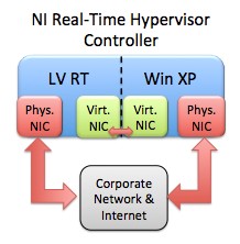
Figure half-dozen. In this scenario, a Real-Time Hypervisor controller is running both Windows XP and LabVIEW Existent-Fourth dimension in parallel. Both OSs are connected to each other through a ready of virtual NICs, and each OS has a physical NIC to connect to the corporate network & internet as well.
In this scenario we will work with a Real-Fourth dimension Hypervisor arrangement that has 2 physical NICs, and has the internal Virtual Ethernet connection enabled. One concrete interface volition be assigned to Windows XP, and the other to LabVIEW Real-Fourth dimension. Therefore, each OS volition accept access to ii NICs (the Virtual Ethernet connection and ane concrete connection). The Windows XP side of the hypervisor arrangement will be used for LabVIEW Real-Time awarding development and deployment.
Assume that the physical connections are used to enable communication to the internet from either OS via a corporate network. The virtual interface will be used merely for communication between LabVIEW Existent-Time and Windows XP. The IP address of both physical adapters connected to the corporate network will be dictated via DHCP, and will be in the range x.0.0.x with subnet mask 255.255.255.0. The gateway accost is set to 10.0.0.1.
Following the guidelines in a higher place, we should set a static IP for each of the Virtual Ethernet adapters using a unlike subnet than is used with the physical adapter on each Os. Although other addresses in the 10.ten.x.x range could be used, to be bourgeois nosotros will set the IP addresses of the Windows XP and LabVIEW Real-Time adapters to 192.168.0.1 and 192.168.0.2 respectively. The subnet mask of each is set to 255.255.255.0.
Considering nosotros desire both Windows XP and LabVIEW Real-Time to admission the internet via the physical NICs, they should be the only adapters that have a default gateway gear up. Therefore, we will leave the default gateway entry for both Virtual Ethernet NICs empty. Note that each Os ultimately has simply 1 default gateway specified.
LV RT
Physical NICLV RT
Virtual NICWin XP
Virtual NICWin XP
Physical NIC IP Address: (DHCP) 10.0.0.x IP Address:
192.168.0.2IP Address:
192.168.0.1IP Address: (DHCP) 10.0.0.ten Subnet Mask: (DHCP) 255.255.255.0 Subnet Mask:
255.255.255.0Subnet Mask: 255.255.255.0 Subnet Mask: (DHCP) 255.255.255.0 Default Gateway: (DHCP) 10.0.0.1 Default Gateway: 0.0.0.0 (unspecified) Default Gateway: 0.0.0.0 (unspecified) Default Gateway: (DHCP) 10.0.0.one
Table 4. This tabular array shows one possible IP address configuration for the system shown in Figure 6 above. Since there are two OSs running on a single hypervisor controller in this case, the of import thing to note is that each OS connects to carve up subnets with each NIC, and a maximum of one default gateway.
Case 3: Configuring an NI Real-Time Hypervisor System with Virtual Ethernet (remote development)
In this scenario, two concrete NICs are also used in a Real-Fourth dimension Hypervisor arrangement with the Virtual Ethernet connection enabled as in Example 2 higher up. However, the physical NIC assigned to LabVIEW Real-Time volition be used for deployment from a networked host PC rather than for internet access.
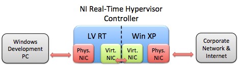
Effigy 7. In this scenario, the LabVIEW Real-Fourth dimension side of an NI Real-Fourth dimension Hypervisor system is connected to a remote Windows PC for LabVIEW Existent-Time awarding development.
The Windows physical adapter will however be assigned a DHCP address in the range ten.0.0.x with subnet mask 255.255.255.0. The Virtual Ethernet adapters on Windows XP and LabVIEW Real-Time will one time once again use static IP addresses of 192.168.0.1 and 192.168.0.2 respectively, with subnet masks of 255.255.255.0 and no default gateway.
To ensure that the physical NIC used with LabVIEW Real-Time is on a different subnet than the Virtual Ethernet NIC, nosotros can use an IP accost of the form 192.168.1.x with subnet mask 255.255.255.0. Therefore, the remote PC adapter and LabVIEW Existent-Time adapter connected together tin utilise static IP addresses of 192.168.1.i and 192.168.ane.2 respectively with subnet masks of 255.255.255.0. Once once again, no default gateway is needed since neither adapter needs to access an outside network (no gateways are nowadays on this subnet).
Win Host
NICLV RT
Concrete NICLV RT
Virtual NICWin XP
Virtual NICWin XP
Physical NIC IP Address:
192.168.1.1 IP Address:
192.168.one.2IP Accost:
192.168.0.2IP Address:
192.168.0.1IP Accost: (DHCP) 10.0.0.x Subnet Mask: 255.255.255.0 Subnet Mask: 255.255.255.0 Subnet Mask:
255.255.255.0Subnet Mask: 255.255.255.0 Subnet Mask: (DHCP) 255.255.255.0 Default Gateway: 0.0.0.0 (unspecified) Default Gateway: 0.0.0.0 (unspecified) Default Gateway: 0.0.0.0 (unspecified) Default Gateway: 0.0.0.0 (unspecified) Default Gateway: (DHCP) 10.0.0.ane
Table 5. With a remote LabVIEW Real-Time evolution machine added to this scenario, IP accost settings must be chosen such that the remote PC can connect with the LabVIEW Real-Time side of the hypervisor system.
Many other configurations are also possible, including using DHCP with the remote development PC and LabVIEW Real-Fourth dimension target (to allow connexion with the net), or using additional NICs in the LabVIEW Real-Time target or remote host computer to connect to the internet.
Case 4: Connecting to Two Routed Networks (advanced)
One more than advanced scenario involves configuring a reckoner (running but one OS this time) with two NICs that communicate with ii local networks. Each network features a gateway that can be used to relay packets to additional outside networks.
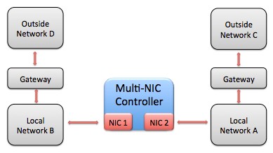
Figure 8. In this advanced scenario, a multi-NIC computer connects to two routed networks. This TCP/IP configuration is more hard to set upward, especially if the outside networks are not supersets of the local network subnets.
Imagine that local network A uses IP addresses of the form 10.0.0.x with subnet mask 255.255.255.0, and local network B uses IP addresses of the form 10.0.1.ten with subnet mask 255.255.255.0. Local network A is connected via a gateway to outside network C, which uses IP addresses of the class 192.168.0.ten with subnet mask 255.255.255.0. Likewise, local network B is connected to exterior network D via a gateway, which uses IP addresses of the form 192.168.one.10 with subnet mask 255.255.255.0.
The goal is for our multi-NIC PC to be able to admission any of the networks. We can connect i NIC to local network A and assign the IP address ten.0.0.5 with subnet mask 255.255.255.0, and we can connect the 2nd NIC to local network B and assign the IP address 10.0.one.five with subnet mask 255.255.255.0. If whatsoever default gateway were assigned, then packets destined for the outside networks may be sent through the incorrect gateway, and and so this is undesirable.
To solve this problem, we tin leave the default gateway entries blank for the two NICs and configure packet routing more manually in the OS. While all OSs are configured differently, near enable the manual addition of routes past the user, and these routes can be configured to persist across reboots of the system. Specifically, we need to add a road with IP address 192.168.0.x and subnet mask 255.255.255.0 to utilise the IP address of the gateway betwixt networks A and C (east.g. x.0.0.1). The aforementioned needs to exist done with IP address 192.168.one.x and subnet mask 255.255.255.0 for the gateway betwixt networks B and D (e.g. accost 10.0.1.ane).
NIC i NIC 2 IP Address: 10.0.0.5 IP Address: 10.0.1.v Subnet Mask: 255.255.255.0 Subnet Mask:255.255.255.0 Default Gateway: 0.0.0.0 (unspecified) Default Gateway: 0.0.0.0 (unspecified) Special Route: Use NIC ane and gateway 10.0.0.ane to road to 192.168.0.x Special Road: Use NIC ii and gateway 10.0.1.1 to route to 192.168.1.x
Tabular array 6. While typically only one NIC in a controller will connect with a gateway (to a corporate network or the internet), more than advanced configurations such every bit the i pictured in Figure 8 above may require special OS routing entries to function properly.
Additional routes may need to exist added equally the number of distinct subnets increases. In practice, most networks are ready up to avoid the need for this circuitous configuration by ensuring that each reckoner is connected to only one gateway.
Source: https://www.ni.com/en-id/support/documentation/supplemental/11/best-practices-for-using-multiple-network-interfaces--nics--with.html
0 Response to "Can Two Network Interfaces Have the Same Ip Address?"
Post a Comment